PDF datasheet (fr)
SyncNet: Picosecond Synchronization System for Long Distance Time / Frequency Transfer
Introduction
Time stamping is of major importance when multiples sampling subsystems have to work together. The FEE's “SyncNet” system was originally conceived for Software Digital Radio (SDR) in a MIMO (Multiple Inputs Multiple Outputs) context by synchronizing HF/VHF digital receive antennas in order to make large phased arrays. It allows a precise time & frequency transfer through optical fibers towards virtually any number of “client” subsystems.
Possible such client subsystems are:- HF/VHF digital receiver dedicated to the digitization at the antenna (mark 1 done, mark 2 on roadmap)
- HF/VHF exciter for digital transmit antenna (project)
- Distributed pulse time stamper / Interval counter / Event generator with 1 ps resolution (project)
- ...
Description
The FEE's SyncNet system uses one fiber per synchronization port and allows hot plug. It is based on low cost optical interface (ethernet SFP modules) used in a specific configuration, and works nominally at a wavelength near the minimum dispersion of the fiber (ie about 1310 nm for an ITU-T-G652 / G657 standard fiber).
While having similarities with CERN's "White Rabbit" synchronization system on ethernet, SyncNet is specifically dedicated to synchronization (data transfer is minor) and such allows much more stability and precision. In particular, it aims to achieve absolute error less than 50ps without installation calibration.
The underlying principle is to compute the global fiber propagation delay through signal reception datation on each side, followed by the measures data exchange. This allows the slave side to evaluate its time shift, which is then injected in a phase-locked loop to align its internal clock to the master side's one.
The absolute error added by a SyncNet link is typically below 20 ps on a 10 km link. Transferred to a 120 MHz carrier, this is equivalent to a phase error of less than 1°.
Two SyncNet parameters sets are used, one for short range (up to 10 km), one for long range (up to 100 km). On long distances, the precision is mainly capped by the wavelength shift between the lasers. From a 3-parameters model of the fiber, the knowledge of the lasers wavelengths,
their temperature dependence (factory calibration) and the estimated fiber global propagation delay, the system compensates most of the propagation delays asymmetry in the fiber.
A SyncNet subsystem has at least one synchronization port (which can be configurated as a master or a slave), and typically two ports to allow redunded schemes. At factory, the calibration procedure measures the laser wavelength and specific delays of each port, which are then numerically compensated.
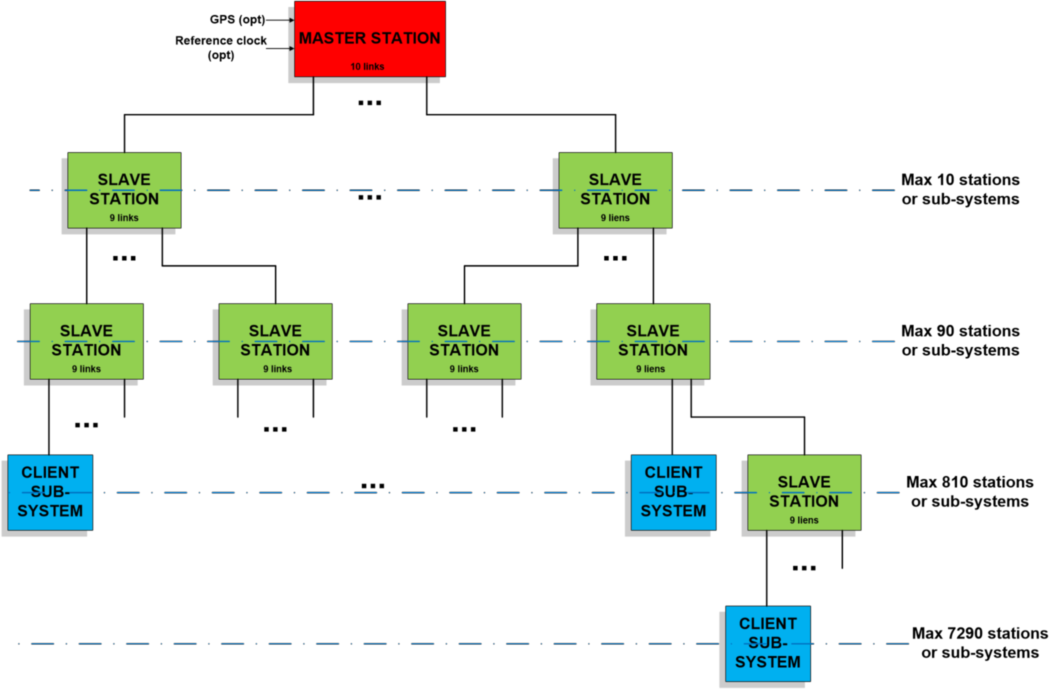
The first element of a SyncNet system is the synchronization station, which allows, through a tree structure, to synchronize any number of slave client subsystems with a minimal number of stages (and minimal cumulated errors). A typical synchronization station has also inputs for external reference signals (high stability OCXO, rubidium- or cesium-based oscillators,…).
An active GPS antenna input enables long term frequency reference management.
The typical synchronization station has 10 SyncNet ports; in the case of a simple distribution scheme (no redundance), the mesh is:
The mark 1 system's development is now terminated, further modifications of SyncNet (mark 2) are on the roadmap, including:
- Global events propagation (radar blanking,…) for a synchronous handling by all subsystems
- Automatic topology retrieving of the synchronization mesh, allowing use of non-tree structures and/or automatic reconfiguration in case of local failure
- Weighted merging of phase measurements of all OCXOs, rubidium,… free-running clocks available in the SyncNet network in order to reduce global wander
- Merging of measurements of all GPS receivers available in the system, in order to compensate the long term drift of the reference clocks in the mesh
- Parallelizing some SyncNet links to reduce measurement noise and then enhance short-term stability
- Enhancement of delay measurement (better precision, lower noise)
- Use of dedicated optical modules to enhance precision and stability
- ...
Performance evaluation (mark 1 system)
The system synchronization stability has evaluated (in lab) through the following testbench:
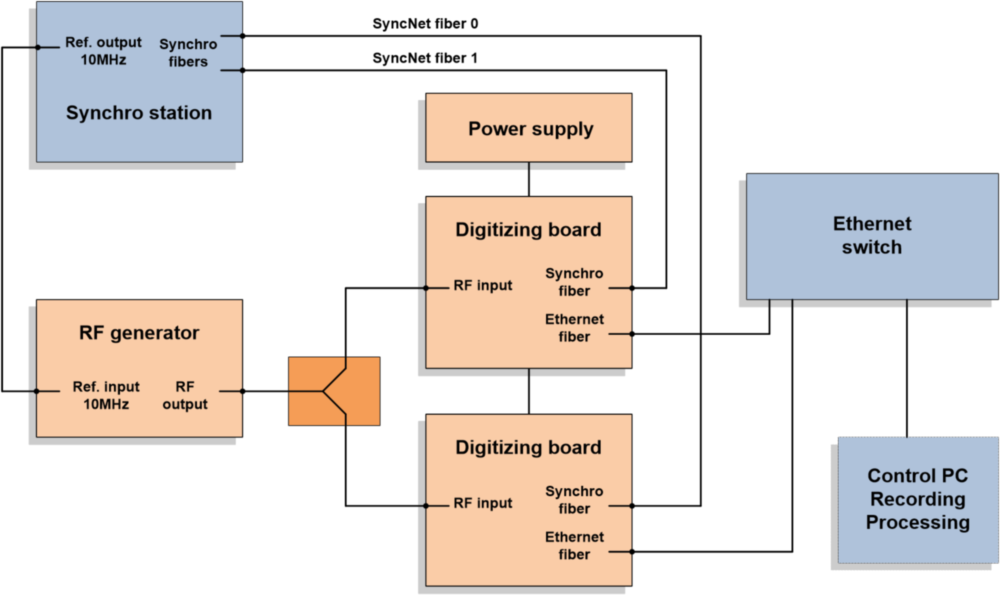
Two digitizing boards are controlled by a SyncNet synchronization station through two optical fibers. A RF generator feeds both boards inputs through a power splitter.
The stability is then evaluated from the differential phase of the signals demodulated by the digitizing boards and recorded by a computer (PC).
The PC extracts phase noise, Allan deviation (ADEV), modified Allan deviation (MDEV) and time deviation (TDEV), characterizing the whole system performance.
The following data are from lab recordings, ambiant temperature is 18-23°C. Fibers lengths are 7 km, SyncNet parameters have been set for short range (10 km max),
and control loop bandwidth to about 50 Hz. The RF signal frequency was 30 MHz. The “absolute” mean delay was estimated to +33 ps (mean of measurements before and after permutation of power splitter outputs;
measurements mean difference was 86 ps). This delay is the sum of the global synchronization error (two SyncNet links) and the digitizing error (two ADCs and input stages synchronization & phase error).
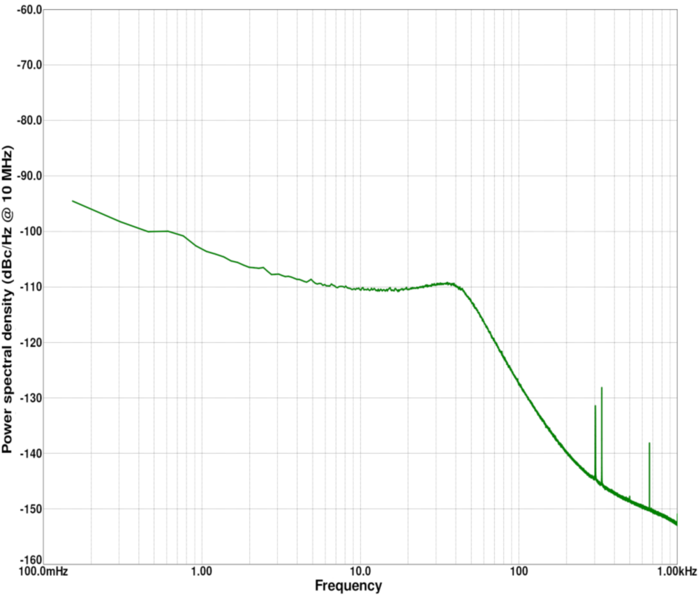
The computed differential phase noise is (short-term, shifted for a 10 MHz reference):
The computed long-term stability of differential delay is (from 160h recording):
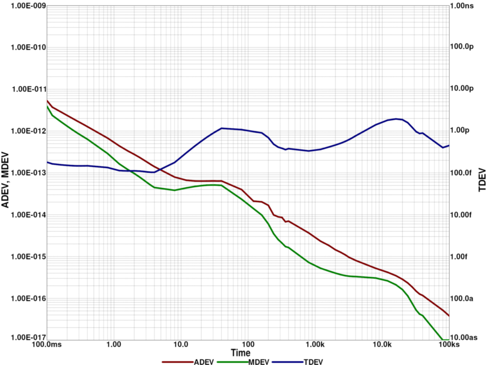
The ~100s and ~10000s –period oscillations are from thermal variations (fans & ambiant).
PDF datasheet (en)PDF datasheet (fr)