
PDF datasheet (fr)
Wideband spectrum video
Feed-forward spatial processing video
DHASA: Digital HF Antenna System for Phased Arrays
Receive antenna arrays allows significant SNR rising through beamforming and/or spatial/polarization diversity, and are required in the HF domain for long range high data rate modulations like WBHF, HFXL,...
Conventional (ie first generation) digital HF receive antenna arrays use locally-synchronized digitizing receivers in the radio shack, connected to active HF antennas through long coaxial cables. The data from the digitizing receivers is then distributed to software-defined radio (SDR) receivers with multi-antenna processing.
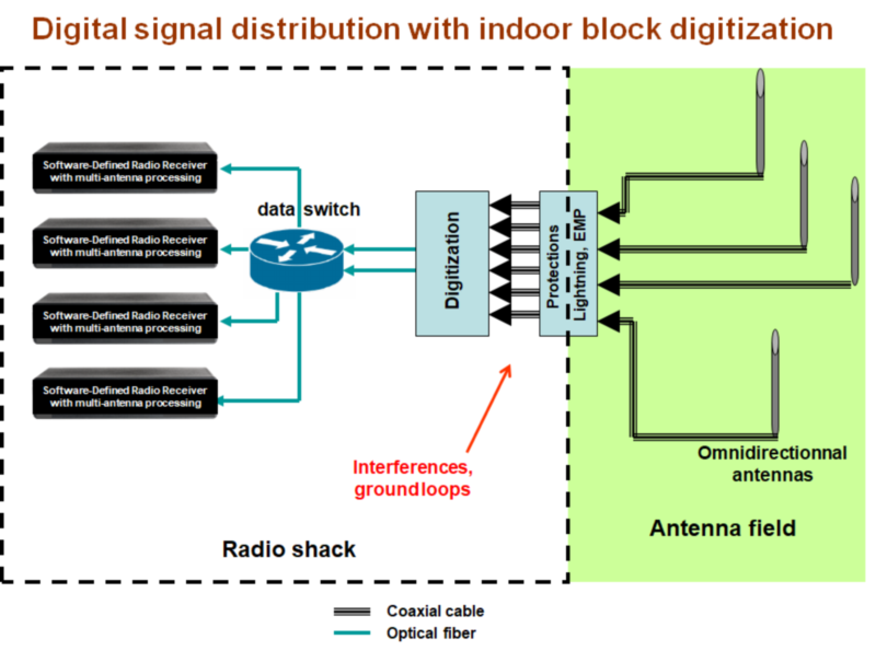
Such configuration has several drawbacks with limit performance, array baseline extension and array-to-shack distance:
- coaxial cables losses
- coaxial cables coupling to antennas
- coaxial cables cost, weight (for non-fixed arrays)
- coaxial cables lengths have to be precisely known (centimeter range), but still temperature-dependant
- antenna calibration drift
- at shack level: interferences, ground loops, coaxial lightning protections required
- ...
With digitization at the antenna level, the coaxial cables can be suppressed and replaced with optical fibers. Of course, power supply is still needed, but its cables have no such constraints than coaxial ones.
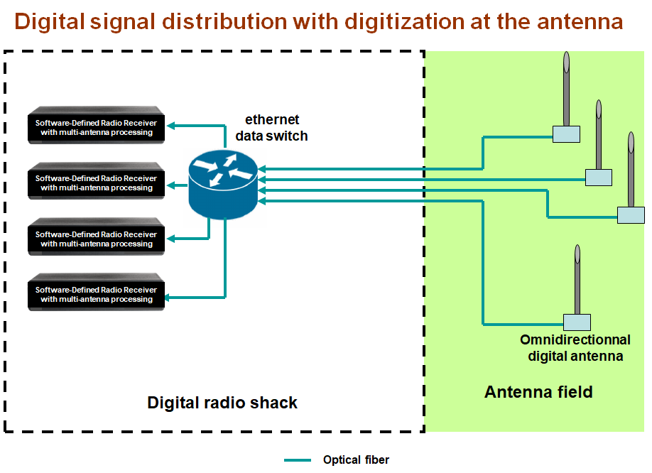
Moreover, with now a calculator at the antenna level, this configuration offers new possibilities:
- antenna digital equalization through auto-calibration
- aerial part's impedance measurement through calibration apparatus, enabling ground plane compensation or defect detection
- precise localization (relative/absolute) and orientation through standard GPS modules
- unlimited shack - array distance
- ...
The main problem of this configuration is the long-range synchronization of the antennas' digitizers. FEE uses its SyncNet synchronization system as the array's backbone:
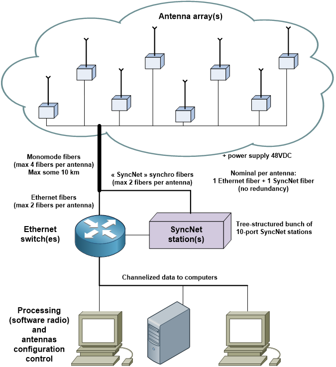
Through the use of FEE's "SyncNet" picosecond synchronization system, antenna auto-calibration and relative positioning systems, long baseline HF receive phased arrays (several km) can then be implemented.
This allows spatial diversity exploitation, along with polarization diversity when vertical and horizontal antennas are mixed in the array.
To ease digitized data exploitation, a channelization is done at the antenna level. Associated with an ethernet multicast distribution, each SDR receiver can ask only for channels of interest.
This is done through standard IGMP protocol between them and the main ethernet switch.
Standard channel in FEE products is 8 kHz wide (both spacing and -3 dB bandwidth), with 10 kHz sampling frequency. Time-stamped complex channel data are provided as standard (IEEE754) 32-bit floating point numbers, and are volt-referenced at the equalized input.
A specific FEE's protocol (ADCP, Antenna Discovery and Control Protocol) relying on UDP/IP is used for configuration, discovery (self-building) and management of the array. A processing unit is needed to manage the array and insures coherent configuration, relative localization calculation,...
It's called "master client" of the array.
"Slave clients" are the SDR receivers, which rely on master client to get current configuration/status of the array; there is no direct talk to antennas.
As a special multicast address is dedicated to array's status information broadcasting by the master client, it has little traffic to manage from the slaves (mainly initial configuration).
The channelized data itself is not handled by the master client, and since ethernet multicasting is used to distribute channelized data, the number of SDR "slave" receivers is not limited.
With full-band channelization, the SDR receivers are autonomous and can listen for any frequency or bandwidth. Higher bandwidth signal reconstruction from elementary channels can be done by an efficient FFT-based preprocessing stage.
The volt-to-SDR receiver latency is depending on the ethernet data packets parameters choosen by the user (one packet = c channels x s time samples).
For a given data packet size, short latencies imply more channels in it, and higher bandwidth required per multicast address.
The ADCP protocol enables redundancy if required (2 physical ethernet networks, and up to 2 master clients).
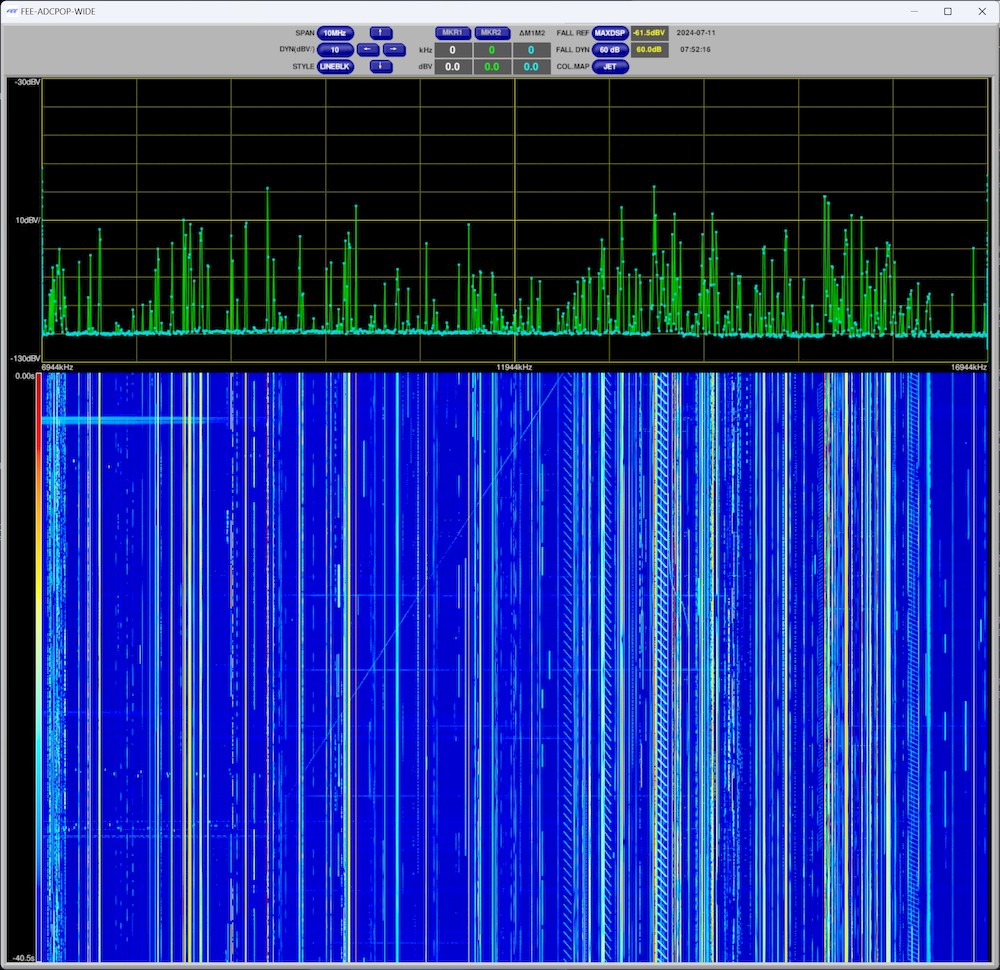
Mainly for monitoring purposes, the FEE digital antennas use an additional multicast address to periodically transmit mean and peak power values for each channel, allowing real-time full HF spectrum visualization (up to 50 fps) at low data rate and minimal computing cost on user side.
Below is a screenshot of a 25 fps video of wideband spectrum provided by one antenna (8 kHz channels):
Following is a screenshot of processing from a 8-antenna protype array: low bandwidth frequency spectrum and MVDR (Capon) spatial spectrum at 15.260 MHz (BBC AM broadcast station from Ascension Island). On spatial spectrum (bottom-right), elevation is 90° at center, decreasing linearly with radius to 0° at edge of disc.
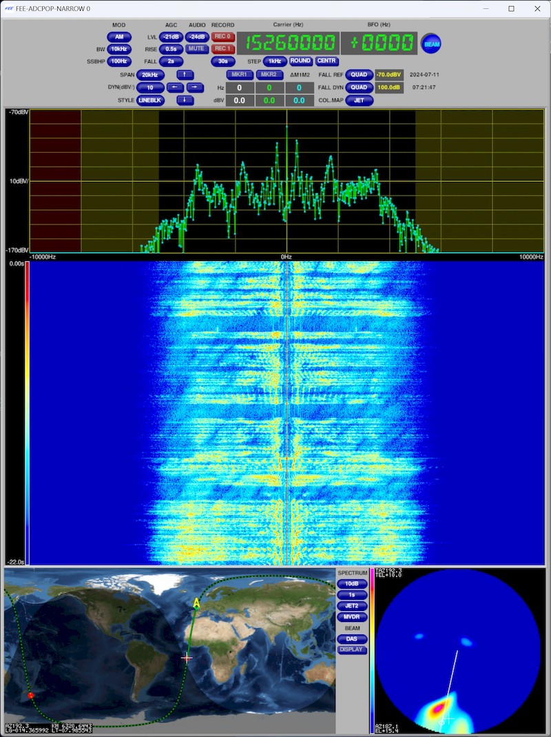
This video shows a simple feed-forward beam processing ("Delay And Sum": all 8 antenna signals rephased in the target direction and summed) to discriminate an AM broadcast station and a digital station.
Main DHASA products are for now:
- Digital receive monopole HF antenna DHAMO
- Digital receive dual horizontal dipole HF antenna DHADI
- Digital HF receiver SYDRE
- 12-port 48V Power Distribution Station DHAPO
- SyncNet distribution station SYDON for antennas synchronisation in arrays
PDF datasheet (en)
PDF datasheet (fr)